

Installing a Pressure Reducing Valve
Why would you install a Pressure Reducing Valve (PRV)?
All devices and items in a Hot Water or Central Heating system are designed to work within a pressure range, for example, a tap that is specified to work in a high pressure water system (aka Mains Pressure) will often be rated to work in a pressure range of 1 Bar to 10 Bar – the domestic mains water in the UK is virtually bound to be within that range and so there would be no need to reduce any pressure for the tap.
Other items may have a lot lower working pressure. The image below shows the specification for a Vented Cylinder. This one is a cylinder with twin heat source coils – one for a Solar Thermal system and one for a Boiler system, plus it has a third coil that is connected to the incoming cold water mains to act as a Heat Transfer coil.
If we look at the Solar Primary and Boiler Primary data, we see that the Maximum Working Pressure is 3.5 Bar.
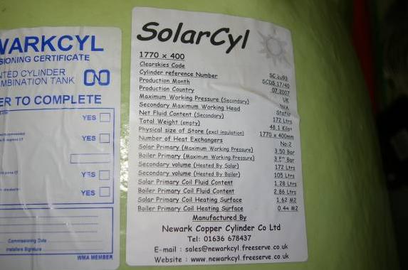
Additionally, although not stated on the label, the manufacturer of this cylinder recommends that the incoming pressure to the Heat Transfer coil when working is set to 3 Bar to efficiency reasons.
The mains pressure to the property where this cylinder is installed is in excess of 5 Bar and thus it would be good practice to be able to set the pressure to no greater than the maximum working pressure of the devices installed that the mains water feeds. To do this, a Pressure Reducing Valve could be installed. It is a common belief that to reduce pressure, you can partially close a valve, but this has no impact on pressure and actually can increase pressure. Imagine using a finger to close up a garden hose end to get a harder spray (in other words, increased pressure) – the same effect happens with a partially closed valve. Note: The term “Pressure Reducing Valve” is slightly misleading. The purpose of a Pressure Reducing Valve (or PRV) is to cap the pressure at a set pressure. If the incoming pressure is variable and above the setting of the PRV, then the pressure output of the PRV will stay at the set value, but should the incoming pressure reduce below the setting, then the output pressure will be same as incoming and not reduced further.
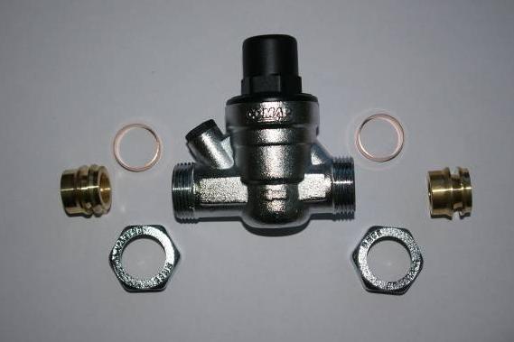
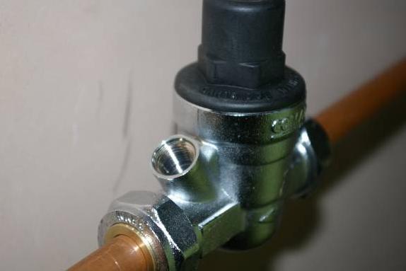
Features of the PRV There are varying designs of PRVs, but they are all similar in design and function. This image shows the Comap PRV – this particular PRV is designed to work with both 15mm and 22mm pipe in the single design by use of brass reducing collars. The key feature to observe common to PRVs are the directional arrow that shows which way to fit the device, the reservoir bowl at the bottom, a cartridge with strainer that is removable by unscrewing the top mechanism, and another small cap (to the left in this PRV) that can be removed to fit a gauge to check the pressure. PRVs should be mounted on horizontal pipe work with the mechanism at the top and reservoir bowl at bottom
The Comap PRV actually comes with a gauge that can be installed.
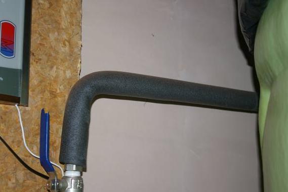
Installing the PRV The location chosen to install the PRV was on a horizontal pipe run that will allow full mains pressure to cold taps but restrict the pressure into the cylinder coil and boiler. The mains supply direction is from the horizontal pipe and down to the lever gate valve
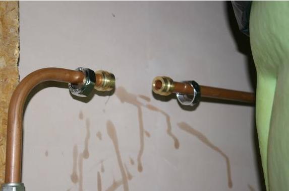
Turn off the mains stop cock and then turn on a cold tap to drain down the remaining water in the pipe as much as possible, then using a pipe slice, cut a suitable gap into the pipe for the PRV to fit into. Here we have 15mm pipework, so the supplied reducing collars were needed to suit the 22mm PRV fittings.
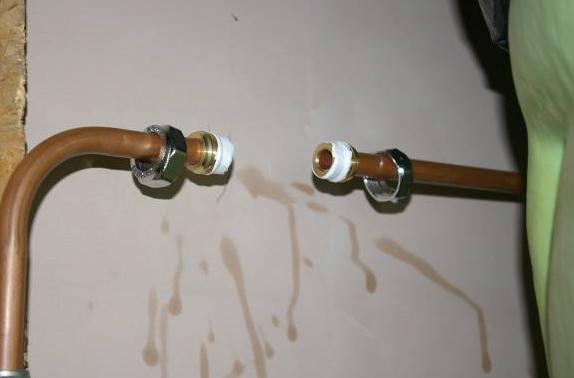
As the 22mm end fitting effectively acts as an olive, a wrap of PTFE tape was also applied as an extra security.
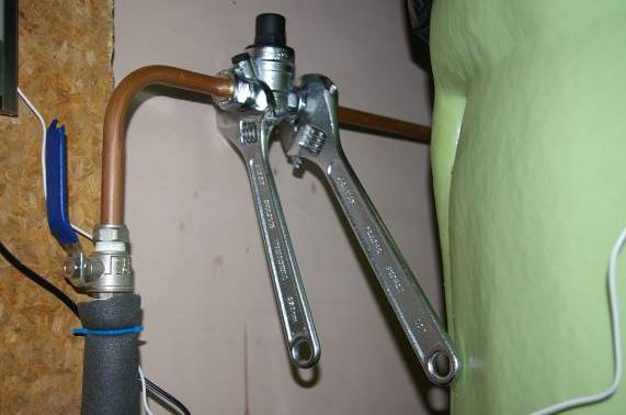
The Nuts were then tightened onto the PRV body, taking care to ensure the PRV is fitted the correct way round! Note that with this particular PRV, the reducing brass collars that slide over the 15mm pipe also incorporate the olive for that 15mm pipe, so the nuts will require a firm hand to tighten sufficiently for the fittings to compress as Brass fittings are considerable stronger then copper– see the “how to” on installing compression fittings for advice if need be. y.
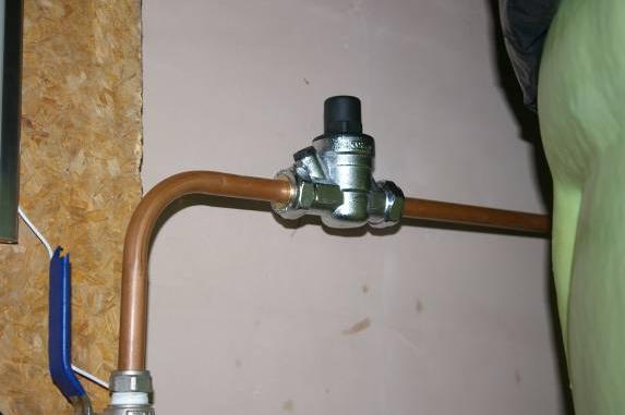
Once tightened, the PRV is fully installed and will be operational
As mentioned, this PRV comes with a gauge and this will now be installed. Remove the cap that covers the gauge fitting (and keep somewhere safe as it would need to be reinstalled if the gauge was removed).
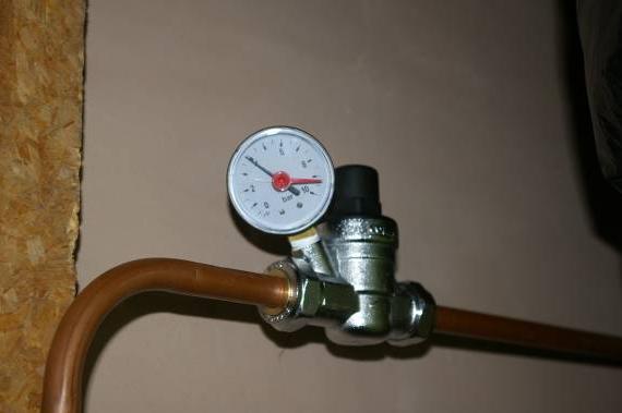
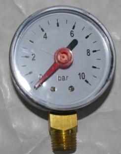
Screw on the gauge. In this case, the gauge will be fully secure when the face is facing the wall, which is not that useful, so a few wraps of PTFE tap will allow the gauge to be tightened and face outwards. The Black arrow shows the output water pressure and the red arrow is a purely visual marker arrow that can be set to indicate anything you like e.g. Incoming water pressure, minimum pressure experienced, etc.
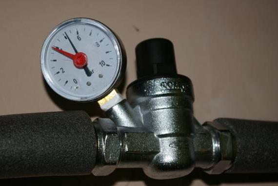
To adjust the outlet pressure, adjust the setting on the PRV following the manufacturers’ instructions to either raise or lower. On this Comap PRV, there is a screw on the top of the black housing that is rotated clockwise or anti-clockwise to either lower or raise the Bar setting. This picture shows the pressure before adjustments. As can be seen, the pressure is a little over 5 Bar. .
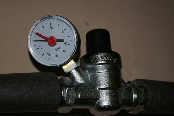
By adjusting the screw at the top of the PRV, this can be increased or decreased as required. The gauge in this picture shows the pressure after adjusting to the desired 3 Bar working pressure setting. .