A shower extractor fan is essential in a room containing a shower in order to prevent condensation. This article will show how to install and wire the extractor fan.
Never work on a live circuit, you must ensure that the circuit that you are working on is isolated and cannot be switched back on accidentally.
Switching off the light at the light switch does not isolate the electricity to the ceiling rose or light fitting. You must isolate the circuit that you are working on from the consumer unit or fuse box!
| Before working on any electrical circuit you must ensure that it is isolated correctly and cannot accidentally be switched back on. Please read the article on safe isolation procedures before doing any electrical work. If you are not 100% certain what you are doing call a qualified electrician. Building regulations are changing all the time and modifying your home electrics could be against new rules and could invalidate your home insurance, if in doubt check first! |
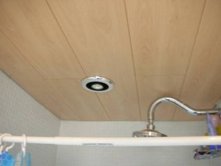
This is a shower extractor fan, this has been specifically designed for use in a shower and it also incorporates a halogen lamp which is 12 volts. Fans like this require additional wiring as both a permanent live and switched live are required as the fan has a built in timer so that it continues to extract air for a set period of time after the light in the room has been switched off.
These fans are wired from the existing light in the shower area and go via a three pole switch to the fan itself. When you operate the shower room light the fan switches on automatically and switches off after a set period of time.
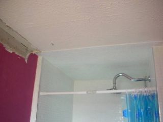
This is the shower where the extractor fan is to be fitted. Cladding is also going to be fitted to the ceiling and so we need to plan where the fan will be fixed and then we can cut away the tiled area for the fan. I have checked the loft above and I have marked out where the fan is to be located.
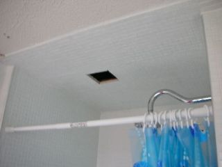
Here I have cut out a section of the ceiling using a plasterboard saw. Normally you would just use a hole saw and power drill and drill through from underneath, but getting through these glass mosaic tiles would be almost impossible.
This hole is in the right place and when the cladding has been fitted I will drill down from above, but only so that the pilot drill (arbour) of the hole saw penetrates the cladding- this is so that I can then drill through from the shower side and get the hole in the exact right place.
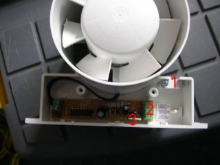
This is the actual fan itself, with the cover removed.. It has an arrow on it and this must be pointing away from the shower.
1. cord grip
2. Terminals- Permanent live, switched live, neutral
3. Time adjuster ( by turning this you can adjust how long the fan stays on for- after you switch the room light off) To wire a shower fan like this you will need some three core and earth cable which is normally 1mm - although there may not be a place to connect the earth wire at the fan!
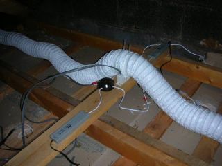
This shows how the fan is arranged. The loft insulation will be replaced later. The fan has been fastened to a piece of timber in the loft and then a flexible 4 inch pipe is connected to one side- this is then connected to the vent that is fixed in the shower area. Ducting is connected to the other side of the fan and this exits the building via a grill which is either fixed into the soffit board/eaves or is vented through a nearby wall. If you are venting through a wall then you will need a diamond core drill. To the right of the picture (out of view) is a transformer which is needed for the 12 volt halogen light.
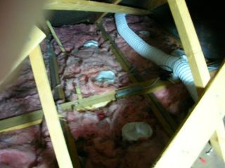
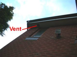
This is what the extractor looks like with the insulation replaced. You can see that the pipe extends right out to the soffit, where it is connected to a vent. The vent pipes simply push over the fan vent connections and the grill vent connections and are held in place with cable ties.
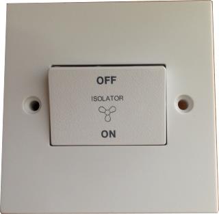
The triple pole isolating switch must be positioned outside of the room containing the shower.
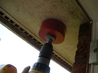
Before you drill this hole ensure that either yourself or someone else can get to the soffit from the inside of the loft in order to connect the vent pipe to. If you cannot access it then you will have to vent through one of the walls. Here I am making the hole in the soffit using a correct sized hole saw and cordless drill. I am doing this by standing with my arm out of the shower room window. This is safer than trying to do it from a ladder, but is still dangerous. The drill can bite and will slip from your hand in an instant, so be aware and be ready not to let go of it.
Ensure that nobody can walk below when you are drilling the hole as dropping a drill from that height could cause severe injuries. If you cannot reach from a window then a scaffold tower is preferred over a ladder. Drilling from a ladder is never a good idea!
Here is the wiring diagram (old colour's)- don't worry it is not that difficult to understand.
This is the way that 90% of houses today are wired up, if yours is different or there is something that you do not understand then please ask in the electric forum Most things are labelled up here apart from the ceiling rose/junction box ( you could have one or the other). I have labelled the terminals in the junction box to help explain what the wires do, once you have looked at it a few times it will become clear. Please bear in mind that your ceiling rose/junction box may have the permanent live, switched live and neutral in different positions as there is no set way of wiring them, you can identify them by the wires going to the terminals.
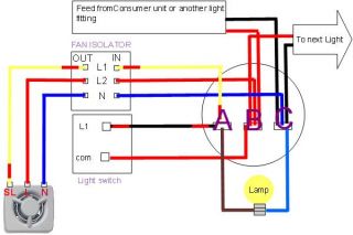
The earth wires have been omitted for clarity, but must be connected.
You can see the feed in and the feed out- ignore these, all you need to know is that-
A is switched live ( it becomes live when the switch is on)
B is permanent live (this is live all the time)
C is Neutral Ignore the two wires going to the Lamp and ignore the two wires going to the light switch. Now it's much easier as you only have six wires (two cables) to think about.
So you now have your fan, a triple pole switch and enough three core and earth cable! Fix the fan to a suitable piece of timber in the loft and then fix the three pole switch, You now need to run the cable in the permitted zones In this diagram we are using the old three core colour's of yellow red and blue, but it is more likely that you will be using Brown, Grey and Black instead now. A wiring diagram is below using the new colour's. The three core cable is connected to the ceiling rose as follows-
| Wire colour | Ceiling Rose | Isolator switch in | Isolator switch out | Extractor fan |
| Blue | NEUTRAL TERMINAL | N | N | N |
| Red | PERMANENT LIVE TERMINAL | L1 | L1 | L |
| Yellow (sleeved Red) | SWITCHED LIVE TERMINAL | L2 | L2 | SL |
Here is the wiring diagram (Harmonised colour's) This is the way that 90% of houses today are wired up, if yours is different or there is something that you do not understand then please ask in the electric forum Most things are labelled up here apart from the ceiling rose/junction box ( you could have one or the other). I have labelled the terminals in the junction box to help explain what the wires do, once you have looked at it a few times it will become clear.
Please bear in mind that your ceiling rose/junction box may have the permanent live, switched live and neutral in different positions as there is no set way of wiring them, you can identify them by the wires going to the terminals.
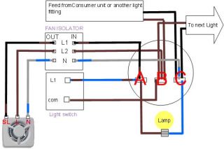
The earth wires have been omitted for clarity, but must be connected.
You can see the feed in and the feed out- ignore these, all you need to know is that-
A is switched live ( it becomes live when the switch is on)
B is permanent live (this is live all the time)
C is Neutral Ignore the two wires going to the Lamp and ignore the two wires going to the light switch. Now it's much easier as you only have six wires (two cables) to think about.
So you now have your fan, a triple pole switch and enough three core and earth cable!
Fix the fan to a suitable piece of timber in the loft and then fix the three pole switch, You now need to run the cable in the permitted zones. The three core cable is connected to the ceiling rose as follows-
| Wire colour | Ceiling Rose | Isolator switch in | Isolator switch out | Extractor fan |
| Grey (sleeved Blue) | NEUTRAL TERMINAL | N | N | N |
| Brown | PERMANENT LIVE TERMINAL | L1 | L1 | L |
| Black (sleeved Brown) | SWITCHED LIVE TERMINAL | L2 | L2 | SL |


